| 2D Passage Wall Modeling
|
| Compass is capable of using the Up, Down, Right, and Left data to generate
models of the passage walls. Compass has the ability to model passage walls
in more than a dozen modes different ways. |
| 2D Modes |
| Compass can model passage in both 2D and 3D modes. The 2D modes are
generally used for creating paper maps, to assist with cartography and
for publication. Click here for information on
the 3D modes. The following images illustrate all the different 2D
passage modeling features: |
| Passage Wall Marking
|
|
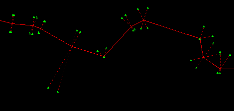 |
| This image illustrates "Wall Marking" mode. In this mode, the locations of the passage walls are marked
relative to the survey station. The dotted lines show the survey station
that mark is associated with. This mode is useful as a basis for making hand-drawn survey maps. They are less cluttered that some other modes which makes
it easy to draw or trace passages over the plot. |
| Polygon Mode
|
|
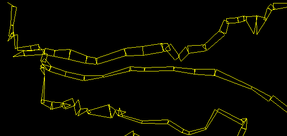 |
| This image shows "Polygon Mode." In this mode, the passage walls are depicted
as polygons. The corners of the polygon represent the Up, Down, Right and
Left points at right angles from each station.
|
| Filled Polygon Mode |
|
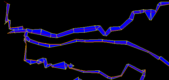 |
| This image shows the "Filled Polygon" mode. In this mode, the polygons are
merged to form a continuous passage and the passage is filled with color of
your choice. This mode is very useful for generating plots for publications.
This is because you can fill the passage with a dark color will show up well
in low quality black and white printing. |
| Spline Curve Models
|
|
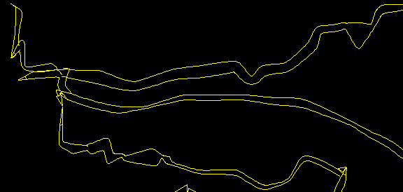 |
| The third image shows "Spline" mode passage modeling. In this mode, the program
uses a spline function to smooth passage wall lines. This creates a much more
realistic passage model. |
| Filled Splines |
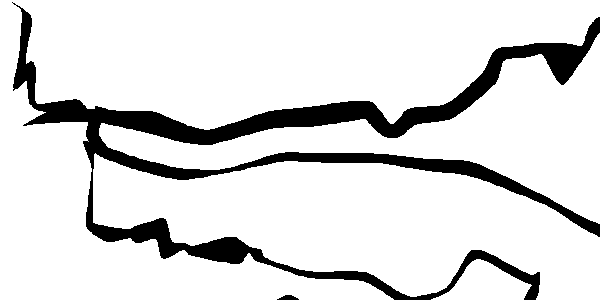 |
| Spline curves use the normal passage information to produce smoothly curving
cave walls that resemble hand drawn maps. The spline curves can be filled
with solid colors to make the individual passages easier to see and visualize.
This mode is very useful for creating maps and topographic overlays for
publication. This is because the filled passage make realistic cave maps
and the solid colors are easy to print in newsletters and journals without
expensive printing processes. |
| Depth Filled Passages
|
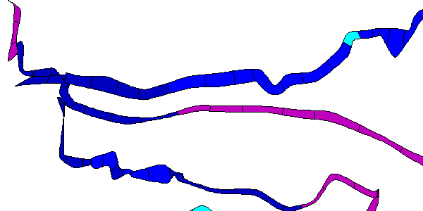 |
| Any of the filled passage modes can be filled with colors that correspond to
the survey depth. The black lines across the passage show each shot segment.
These lines can be removed to give an even smoother passage image. |
| Hidden Line Removal
|
|
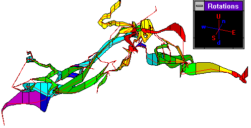 |
| Normally, when Compass plots cave passages, they are plotted in the same
order they were surveyed. This works fine when you are just plotting lines,
but when you are plotting filled passages, you want passages that are far always from the computer screen to be plotted first and nearby passages to be
plotted last. Otherwise far away passages will appear to be on top of
near by passages. COMPASS uses a special process called the Binary
Space Partition to plot the passage in the correct order. This is image is a plot of Fulford cave rotated so it is easy to see that
nearby passages are plotted on top of distant passages. |
| Shaded Cylinders |
|
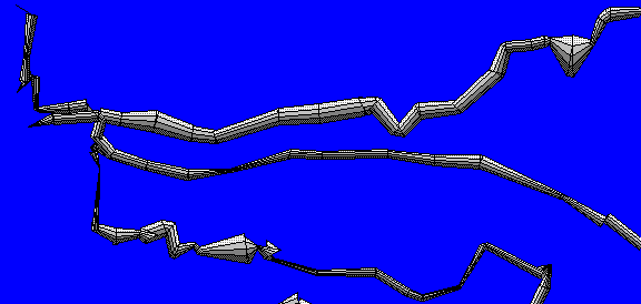 |
| This image shows the "Shaded Cylinders" mode. In this
mode, the passage walls are converted to three dimensional cylinders and
shaded as though the light were coming from above. This makes the passage
walls appear as three dimensional objects. Note: This is not a true 3D
mode. For information about the 3D modes of Compass,
click here. |